

Introduction
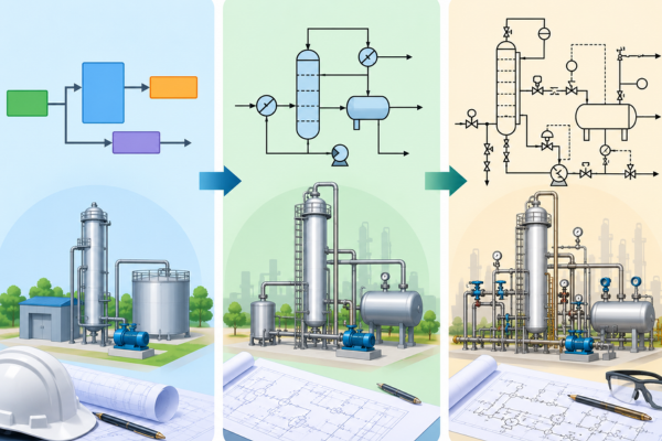
In process engineering, several types of diagrams are used to represent a process at different stages of design and development. Among the most common are the Block Flow Diagram (BFD), Process Flow Diagram (PFD), and Piping and Instrumentation Diagram (P&ID).
These three diagrams are often confused because they describe the same underlying process. However, they are not interchangeable. The primary difference is their purpose, level of detail, and the type of engineering information they communicate.
A simple way to understand them is:
BFD = Process concept
PFD = Process engineering
P&ID = Piping, instrumentation and control
As a project moves from concept toward detailed engineering, information becomes progressively more specific.
What Is the Difference Between BFD, PFD and P&ID?
The easiest way to understand the difference is to compare what each diagram is designed to communicate.
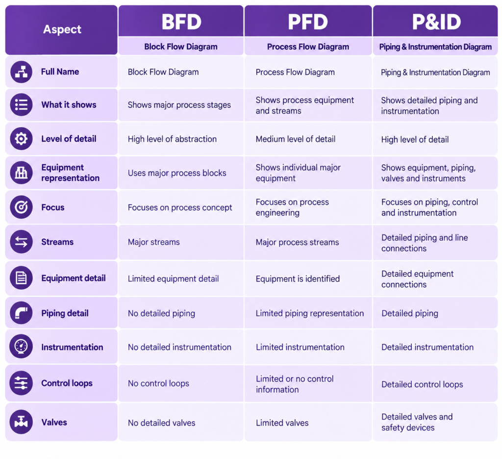
The key difference is therefore not simply what the diagrams contain, but how much information they are expected to communicate.
How BFD, PFD and P&ID Relate to Each Other
BFD, PFD, and P&ID are not completely independent documents. They represent progressively increasing levels of process definition.
A simplified relationship is:
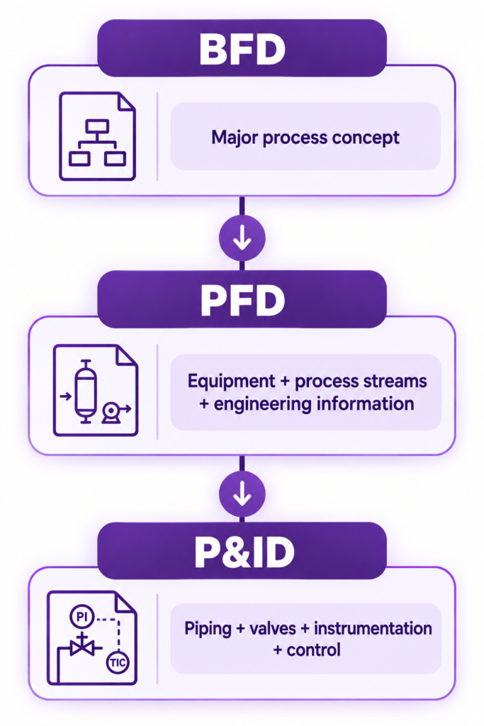
The BFD establishes the overall process concept. The PFD develops that concept by identifying major equipment and process streams. The P&ID then takes the process to a much more detailed level by defining piping connections, valves, instrumentation, and control elements.
This progression makes it easier for different engineering disciplines to work from the same developing process definition.
What Is a Block Flow Diagram (BFD)?
A Block Flow Diagram, or BFD, is a high-level representation of a process.
Instead of showing every piece of equipment, valve, or instrument, a BFD groups parts of the process into major blocks.
For example, a simple water treatment process could be represented as:
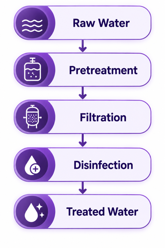
The primary purpose of this diagram is to communicate the overall process sequence.
A BFD is useful during the early stages of process development because it allows engineers and other stakeholders to understand what happens in the process without being overwhelmed by detailed engineering information.
The focus is therefore:
What happens in the process?
What Is a Process Flow Diagram (PFD)?
A Process Flow Diagram (PFD) provides more engineering detail than a BFD.
Instead of representing an entire process section as a single block, a PFD can identify the major equipment involved and show the major process streams connecting them.
For example:
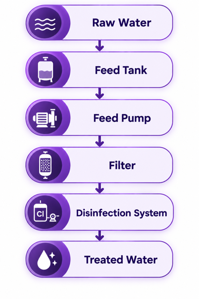
The PFD provides a clearer picture of the equipment involved in the process and how material moves between major process units.
Depending on the project, a PFD may also be associated with information such as process stream data, mass balances, energy balances, and equipment-related information.
The focus becomes:
What equipment and process streams make the process happen?
What Is a P&ID?
A Piping and Instrumentation Diagram (P&ID) takes the process to a much more detailed level.
It describes how the process is physically connected from a piping and instrumentation perspective.
For example, a simplified P&ID representation could show:
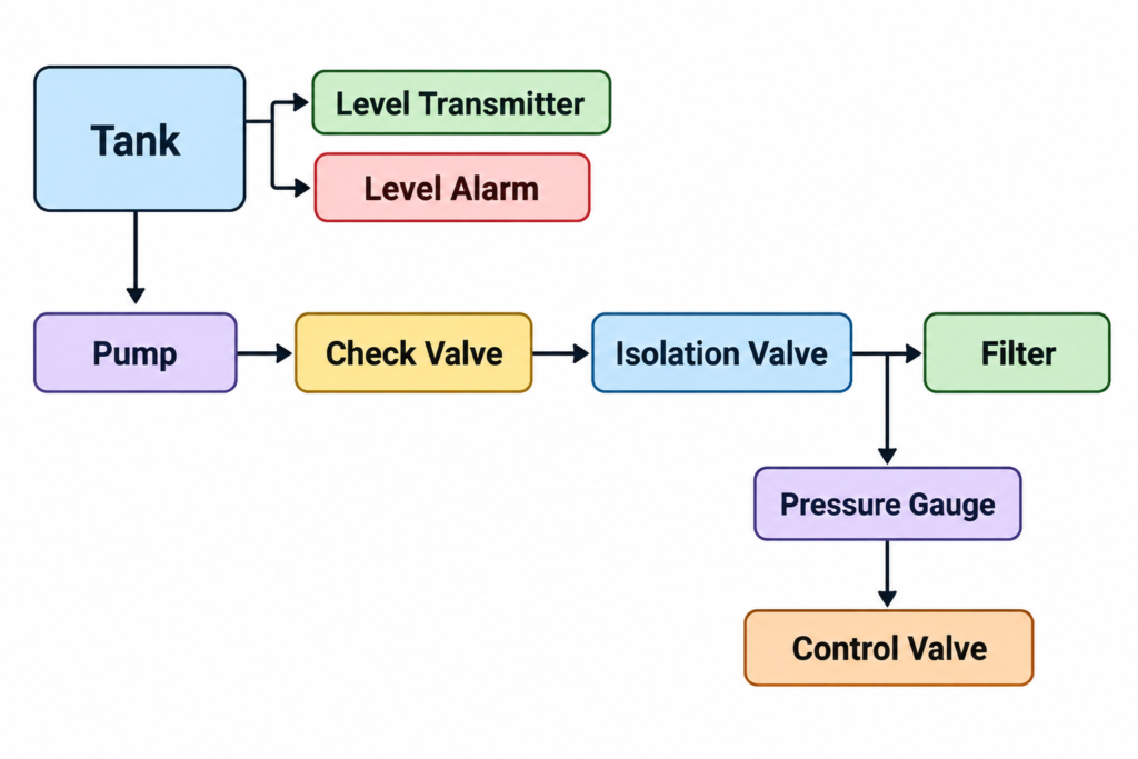
Unlike the BFD and PFD, the P&ID can show individual piping connections, valves, instruments, control elements, drains, vents, alarms, and safety devices.
The focus becomes:
How is the process connected, controlled, instrumented, and protected?
BFD vs PFD vs P&ID: Level of Detail
The difference can also be understood as a level-of-detail pyramid.
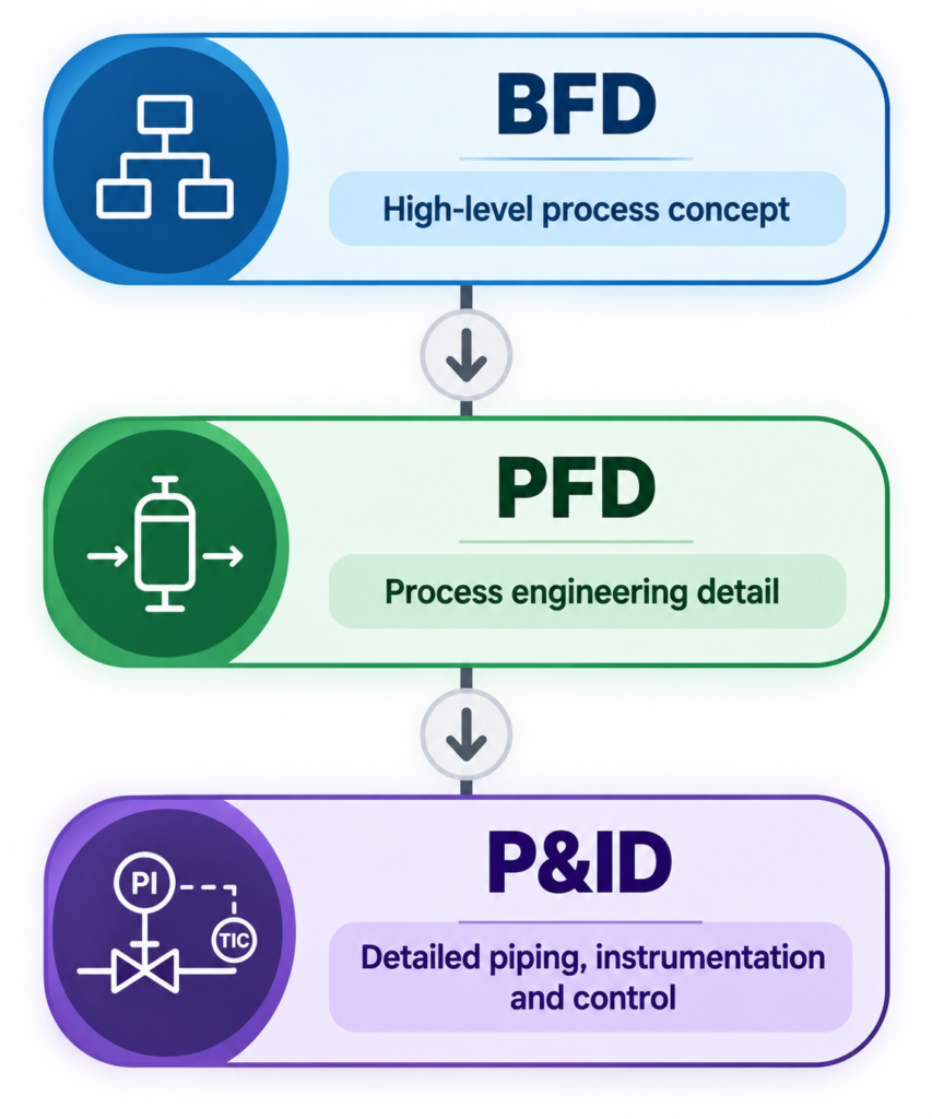
As you move from BFD → PFD → P&ID, several types of information increase:
- Process detail increases
- Equipment detail increases
- Stream detail increases
- Piping detail increases
- Instrumentation detail increases
- Control detail increases
This does not mean that every project will follow exactly the same documentation structure. The actual content and workflow can vary depending on the industry, project requirements, and engineering standards.
BFD vs PFD: What Is the Difference?
The primary difference between a BFD and PFD is the level of process and equipment definition.
A BFD focuses on major process stages and intentionally groups equipment into process blocks.
A PFD provides more engineering detail by identifying major equipment and the process streams connecting them.
For example:
BFD:
Raw Water → Treatment → Filtration → Disinfection → Treated Water
PFD:
Raw Water → Feed Tank → Pump → Filter → Disinfection System → Treated Water
Therefore:
BFD explains the process concept.
PFD develops that concept into process engineering detail.
PFD vs P&ID: What Is the Difference?
The difference between a PFD and P&ID is primarily the level of detail related to piping, instrumentation, and control.
A PFD focuses on major process equipment and streams. It does not normally need to represent every valve, instrument, piping branch, or control loop.
A P&ID goes much further.
It can show:
- Process and utility piping
- Pipe numbers
- Pipe sizes
- Valves
- Instruments
- Control loops
- Alarms
- Safety devices
- Drains and vents
- Equipment connections
Therefore:
PFD explains the process and major equipment.
P&ID explains how the process is piped and controlled.
What Should Not Be Confused?
BFD Is Not Simply a Simplified PFD
Although a BFD contains less information than a PFD, its purpose is different.
A BFD intentionally abstracts equipment and represents the process through major blocks. It is primarily concerned with communicating the overall process concept.
PFD Is Not a P&ID
A PFD does not need to show every valve, instrument, piping branch, or control loop.
Its purpose is to communicate the major process flow and equipment relationships.
P&ID Is Not a Layout Drawing
A P&ID represents functional connectivity and instrumentation. It is generally schematic rather than a precise representation of the physical location of equipment within the plant.
Detailed physical arrangement is addressed through other engineering drawings and models.
How Engineering Documents Progress
A typical process-engineering workflow can be represented as:
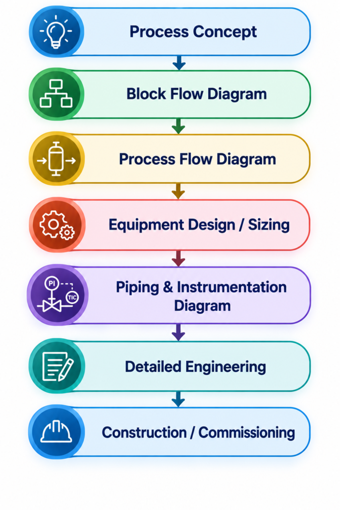
The exact workflow can vary depending on the industry, project type, engineering contractor, and project requirements.
However, the general principle remains the same: information becomes progressively more detailed and specific as the project moves toward detailed engineering.
Why Are BFD, PFD and P&ID Important?
Each diagram serves a different purpose within the engineering process.
A BFD helps communicate the overall process concept to engineers, project teams, and stakeholders.
A PFD provides a stronger engineering understanding of major equipment and process streams.
A P&ID becomes a detailed reference for piping, instrumentation, control, safety, operations, maintenance, construction, and commissioning.
Together, these documents help different teams understand the same process at the appropriate level of detail.
Rather than viewing them as competing diagrams, it is better to view them as different layers of process definition.
A Simple Way to Remember BFD vs PFD vs P&ID
The entire difference can be summarized using three questions:
BFD → What happens?
It communicates the major stages of the process.
PFD → What equipment makes it happen?
It identifies major equipment and process streams.
P&ID → How is it connected and controlled?
It shows detailed piping, valves, instrumentation, control, and protection.
This three-question framework provides a simple way to understand the relationship between the three engineering diagrams.
Key Takeaway
BFD, PFD, and P&ID represent progressively increasing levels of process definition.
A Block Flow Diagram explains the process concept at a high level.
A Process Flow Diagram adds major equipment, process streams, and engineering information.
A Piping and Instrumentation Diagram provides detailed information about piping, valves, instrumentation, control loops, and safety-related elements.
The simplest mental model is:
BFD → What happens?
PFD → What equipment makes it happen?
P&ID → How is it connected and controlled?
Understanding this progression makes it easier to interpret engineering documentation and recognize which diagram is appropriate for a particular stage of process design and engineering.

Lorem Ipsum is simply dummy text of the printing and typesetting industry. Lorem Ipsum has been the industry’s standard dummy text ever since the 1500s, when an unknown printer took a galley of type and scrambled it to make a type specimen book. It has survived not only five centuries, but also the leap into electronic typesetting, remaining essentially unchanged. It was popularised in the 1960s with the release of Letraset sheets containing Lorem Ipsum passages, and more recently with desktop publishing software like Aldus PageMaker including versions of Lorem Ipsum.