
Introduction
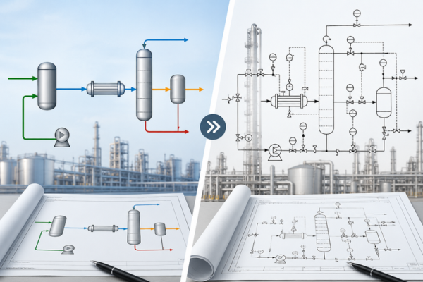
In process engineering, diagrams are essential for understanding how a process works and how equipment, pipelines, and control systems interact. Two of the most commonly used engineering diagrams are the Process Flow Diagram (PFD) and Piping and Instrumentation Diagram (P&ID).
Although both diagrams represent process systems, they serve different purposes and provide different levels of detail.
So, what is the difference between a PFD and a P&ID?
A PFD provides a high-level overview of the major process flow, while a P&ID provides a detailed representation of piping, equipment, instrumentation, valves, and control systems.
Understanding the difference between PFD and P&ID is important for engineers, designers, operators, and project teams working across process industries such as oil and gas, chemical, pharmaceutical, power, water treatment, and manufacturing.
What Is a Process Flow Diagram (PFD)?
A Process Flow Diagram (PFD) is a simplified engineering drawing used to show the overall flow of a process.
It focuses on the major equipment and the movement of materials through the process. A PFD helps engineers and other stakeholders quickly understand how a process operates from start to finish.
A typical PFD may show:
- Major process equipment
- Process streams
- Flow direction
- Main pipelines
- Equipment identification numbers
- Flow rates
- Temperature and pressure
- Material composition
- Basic operating conditions
For example, in a water treatment process, a PFD may show the flow from a raw water tank to a filtration system, followed by treatment units and finally a clean-water storage tank.
The purpose is not to show every valve or instrument. Instead, the PFD provides a clear process-level picture.
Why Is a PFD Used?
PFDs are commonly used during:
- Process design
- Concept development
- Feasibility studies
- Process optimization
- Engineering reviews
- Project discussions
- Equipment sizing
Because a PFD contains less detail than a P&ID, different teams can more easily understand the overall process without getting into detailed control or piping information.
What Is a P&ID?
A Piping and Instrumentation Diagram (P&ID) is a detailed engineering drawing that represents the relationships between piping, process equipment, valves, instruments, and control systems.
While a PFD explains what the process does, a P&ID provides much more information about how the process is physically connected and controlled.
A typical P&ID may include:
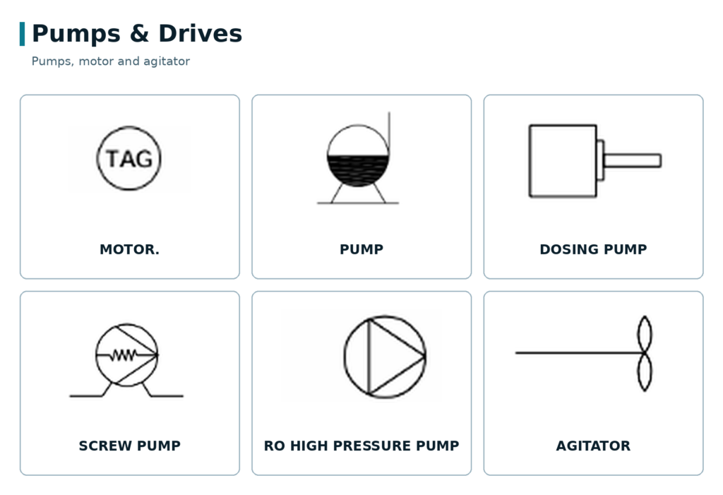
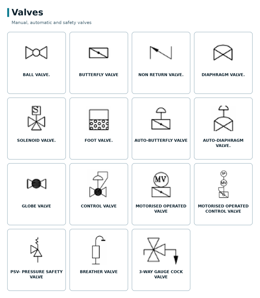
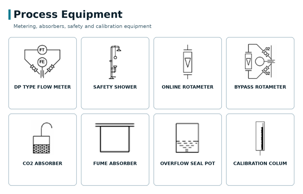
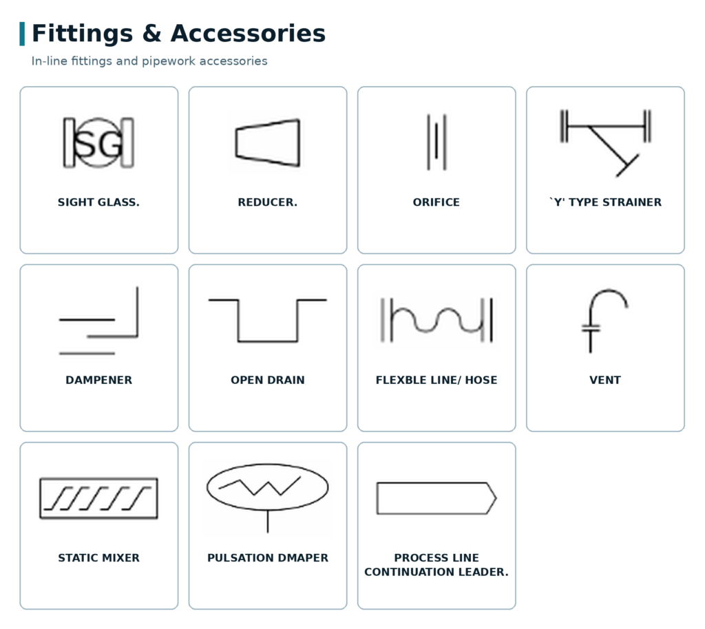
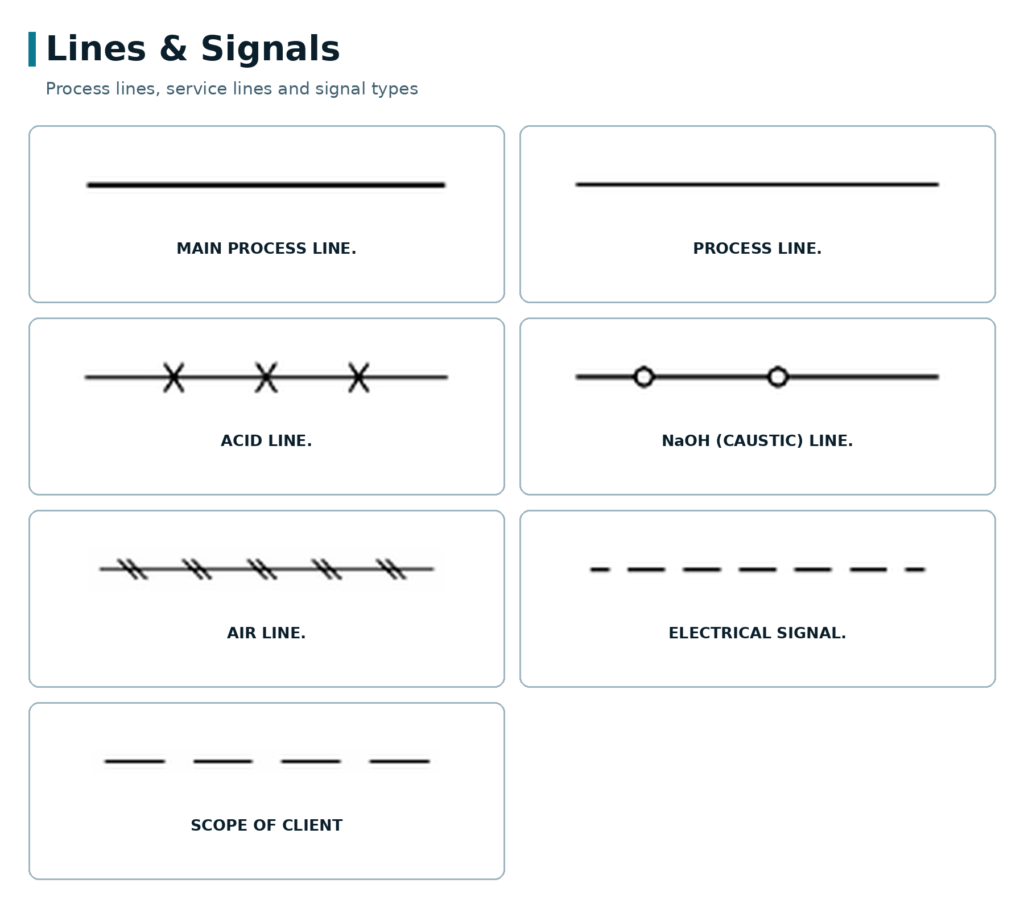
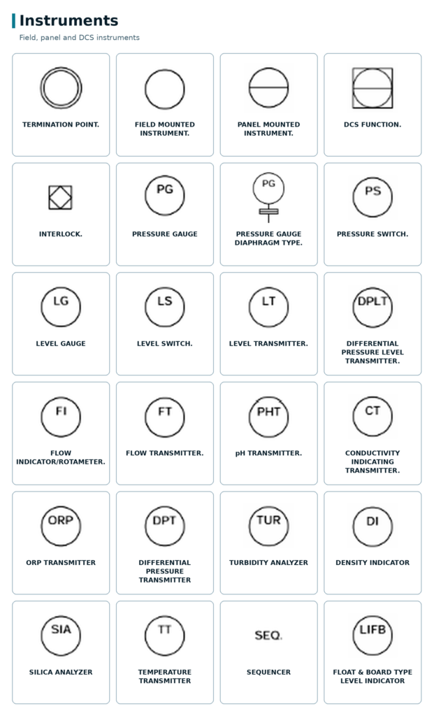
For example, a PFD might simply show a pump transferring liquid from one vessel to another. The corresponding P&ID can show the pump, suction and discharge piping, isolation valves, check valves, pressure instruments, flow instruments, control valves, and associated control loops.
This makes the P&ID much more detailed and useful for engineering and operational activities.
PFD vs P&ID: Key Differences
The main difference between PFD and P&ID is the level of detail and purpose.
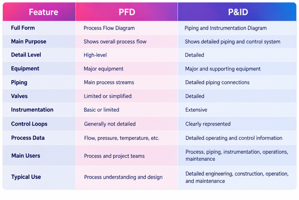
The easiest way to remember the difference is:
PFD = Process overview
P&ID = Detailed process, piping, and instrumentation
PFD vs P&ID: Level of Detail
One of the biggest differences between a PFD and P&ID is the amount of information they contain.
A PFD is designed to communicate the overall process concept. It usually focuses on major equipment and the primary flow paths.
A P&ID goes several levels deeper. It provides the information needed to understand how equipment is connected, how fluids move through the system, and how the process is monitored and controlled.
For instance, a PFD may represent a heat exchanger as a single piece of equipment connected to process streams.
A P&ID may additionally identify:
- Inlet and outlet piping
- Isolation valves
- Bypass lines
- Temperature instruments
- Pressure instruments
- Control valves
- Drain and vent connections
- Equipment tags
- Associated control loops
Therefore, a P&ID is generally much more useful when detailed engineering decisions are required.
When Is a PFD Used?
A PFD is commonly developed during the early stages of process design.
It helps teams answer questions such as:
- What is the overall process?
- What are the major process stages?
- Which equipment is required?
- How does material move between equipment?
- What are the major process conditions?
PFDs are also useful when presenting a process to stakeholders who may not need detailed engineering information.
Because of its simplified structure, a PFD can make complex processes easier to understand.
When Is a P&ID Used?
P&IDs become particularly important during detailed engineering and project execution.
They can support:
- Detailed engineering design
- Piping design
- Instrumentation design
- Control system development
- Safety reviews
- Construction
- Commissioning
- Plant operation
- Maintenance
- Troubleshooting
A P&ID can also serve as an important reference throughout the lifecycle of a process facility.
For example, during maintenance, engineers may refer to a P&ID to understand where a valve, instrument, or piece of equipment is located within the process system.
How PFD and P&ID Work Together
PFD and P&ID should not be viewed as competing documents. They are complementary engineering documents that provide different levels of process information.
The PFD generally establishes the overall process flow and major equipment arrangement.
The P&ID then builds upon this information by adding detailed piping, valves, instrumentation, and control information.
A simplified workflow can be understood as:
Process Concept → PFD → Detailed Engineering → P&ID → Construction & Operation
The exact development sequence can vary depending on the project, but the two diagrams are closely connected throughout engineering design.
PFD vs P&ID: Which One Should You Use?
The answer depends on what information you need.
If you want to understand the overall process, a PFD is usually the better starting point.
If you need to understand detailed piping, instrumentation, valves, and controls, a P&ID is more appropriate.
For example:
- Need to explain the overall process to a project stakeholder?
Use a PFD. - Need to identify a control valve or instrument?
Use a P&ID. - Need to understand the major equipment and process streams?
Use a PFD. - Need detailed information for construction or maintenance?
Use a P&ID.
Conclusion
Understanding PFD vs P&ID is essential for anyone involved in process engineering and industrial projects.
A Process Flow Diagram (PFD) provides a high-level view of the process, showing major equipment, process streams, and key operating information.
A Piping and Instrumentation Diagram (P&ID) provides a much more detailed view, showing piping, valves, instruments, control loops, and other important engineering information.
In simple terms:
PFD explains how the process flows.
P&ID explains how the process is connected, monitored, and controlled.
Both diagrams play an important role in moving a project from process concept to detailed engineering, construction, commissioning, and operation.
Once the difference between PFD and P&ID is clear, it becomes much easier to understand where each drawing fits within the overall engineering workflow.

With nearly two decades of experience in engineering, I bring deep expertise across both EPC (Engineering, Procurement, and Construction) and product-based OEM environments. My core strengths lie in engineering standardization, process optimization, and technical leadership. I have consistently driven excellence through the development and implementation of robust engineering frameworks, delivering value across global industrial projects and complex product lifecycles.