
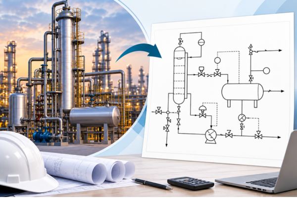
Introduction
In process engineering, understanding how a process works is only one part of designing and operating a plant. Engineers also need to understand how equipment is connected, how fluids move through piping, how processes are controlled, and how the system is protected against unsafe conditions.
This is where a P&ID diagram becomes essential.
P&ID stands for Piping and Instrumentation Diagram. It is one of the most detailed engineering drawings used to represent the relationship between process equipment, piping, valves, instruments, control systems, and safety devices.
Unlike a Process Flow Diagram (PFD), which primarily communicates the overall process flow and major equipment, a P&ID provides a much more detailed view of the piping, instrumentation, control, isolation, and protection systems.
In simple terms, a P&ID helps answer:
How is the process piped, controlled, instrumented, and protected?
What Is a P&ID Diagram?
A P&ID diagram is a schematic representation of a process system showing the connections between equipment, piping, valves, instrumentation, and control elements.
It does not attempt to reproduce the physical plant exactly as it appears in the real world. Instead, it provides an engineering representation of how different components interact within the process.
A typical P&ID drawing may show:
- Process equipment
- Process and utility piping
- Valves
- Instruments
- Control loops
- Alarms and switches
- Safety devices
- Drains and vents
- Process connections
- Flow directions
- Equipment and line identification
Because of this level of detail, P&IDs are used throughout the engineering lifecycle, from detailed design and construction to commissioning, operation, maintenance, and plant modifications.
What Does a P&ID Show?
A P&ID can contain many different types of engineering information. The exact content can vary depending on the project, industry, and applicable engineering standards.
Equipment
- Pumps
- Tanks
- Vessels
- Reactors
- Heat exchangers
- Compressors
- Columns
- Filters
- Separators
Piping
- Process lines
- Utility lines
- Branch lines
- Pipe numbers
- Pipe sizes
- Flow direction
- Connections
Valves
- Isolation valves
- Control valves
- Check valves
- Relief valves
- Drain valves
- Vent valves
Instrumentation
- Pressure transmitters
- Temperature transmitters
- Flow transmitters
- Level transmitters
- Control valves
- Controllers
- Alarms
- Switches
These elements show how process conditions are monitored and controlled within the system.
Understanding Control Loops in a P&ID
One of the key features that distinguishes a P&ID from a basic process diagram is its representation of control loops.
Consider a simple flow-control system:
Process → Flow Measurement → Flow Controller → Control Valve → Process
This shows more than simply how fluid moves through a system. It explains how the process is measured and controlled.
The control sequence can be understood as follows:
- The process flow is measured.
- The measurement is sent to a controller.
- The controller compares the measured value with the desired value.
- A control signal is generated.
- The control valve is adjusted.
- The process flow is regulated.
This relationship between measurement, control, and final control elements is an important part of process control design.
Safety and Protection in P&ID Diagrams
Safety is another important aspect represented in many P&IDs.
Depending on project standards and documentation requirements, a P&ID may include safety-related devices and connections such as:
- Pressure relief valves
- Emergency shutdown valves
- High and low alarms
- Interlocks
- Drains
- Vents
- Safety instrumented functions
These elements help engineers understand how the process is protected against abnormal operating conditions.
However, a P&ID should not be considered a complete safety document by itself. Additional safety studies and documentation may be required depending on the project and its engineering requirements.
What Does a P&ID Not Primarily Represent?
Although a P&ID contains significant engineering detail, it is important to understand its limitations.
A P&ID is generally not intended to provide:
- Detailed 3D equipment geometry
- Fabrication drawings
- Exact physical equipment locations
- Structural details
- Building layouts
- Complete electrical design
- Full cable routing
These requirements are normally addressed through other engineering drawings, models, schedules, and documents.
For example, a 3D plant model provides a better representation of physical equipment arrangement, while electrical drawings provide detailed information about electrical systems and cable routing.
P&ID vs PFD: What Is the Difference?
One of the most common questions in process engineering is the difference between a PFD and P&ID.
A Process Flow Diagram (PFD) provides a higher-level view of the process. It focuses on major equipment, process streams, and the overall movement of materials through the system.
A P&ID diagram, in contrast, goes into much greater detail about piping, valves, instruments, control loops, and safety-related elements.
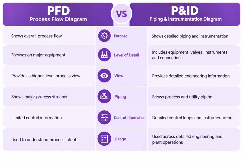
A simple way to remember the difference is:
PFD = What happens in the process?
P&ID = How is the process piped, controlled, instrumented, and protected?
Why Is a P&ID Important?
A P&ID drawing serves as a common engineering reference for multiple disciplines.
It helps answer questions such as:
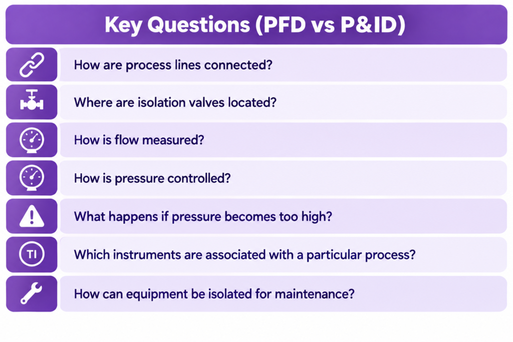
Because it combines piping, instrumentation, control, and safety information, a P&ID supports many engineering and operational activities.
Detailed Engineering
Process and engineering teams use P&IDs to translate process requirements into detailed system information.
Piping Design
Piping engineers use P&IDs as an important reference when developing piping systems and related engineering deliverables.
Instrumentation Design
Instrumentation engineers use P&IDs to identify instruments, control loops, measurement points, and control requirements.
HAZOP and Safety Reviews
P&IDs provide an important reference during HAZOP studies and safety reviews, helping teams examine process deviations, safeguards, and potential hazards.
Operations
Operators can use P&IDs to understand how equipment, piping, valves, and control systems interact during plant operation.
Maintenance
Maintenance teams can refer to P&IDs when identifying equipment connections, isolation points, drains, vents, and related components.
Commissioning and Construction
During construction and commissioning, P&IDs can help teams verify that installed systems correspond with the intended engineering design.
Plant Modifications
When an existing plant needs to be modified, P&IDs provide a reference for understanding the existing process and identifying affected systems.
P&ID as a Detailed Engineering Reference
A P&ID often becomes a shared reference across multiple engineering disciplines.
For example:
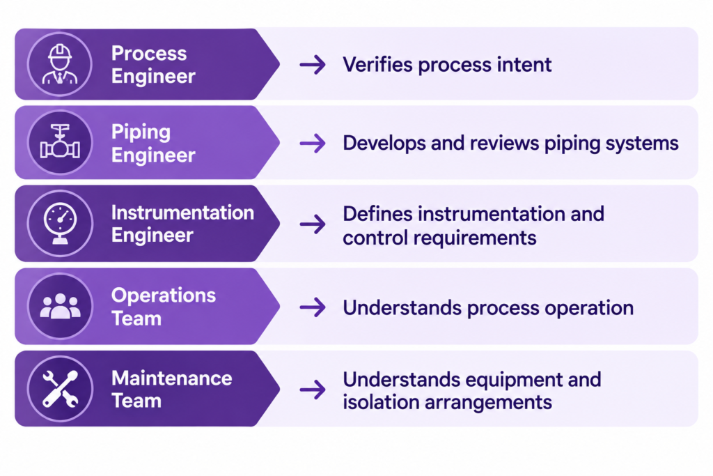
This makes a P&ID more than just a drawing. It acts as a common language between different engineering and plant teams.
Common P&ID Symbols and Tags
P&IDs use standardized symbols, abbreviations, and identification systems to represent equipment and instrumentation.
Common process variables include:
- F – Flow
- P – Pressure
- T – Temperature
- L – Level
These letters may be combined with other identifiers to represent transmitters, controllers, indicators, switches, and alarms.
However, the exact symbols, tag conventions, and standards can vary between companies and projects. Engineers should therefore refer to the applicable project standards, legend, and engineering specifications when interpreting a P&ID.
P&ID in the Engineering Workflow
A P&ID typically sits between high-level process definition and detailed engineering deliverables.
A simplified workflow is:
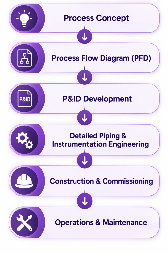
The P&ID therefore plays an important role in translating the overall process concept into a more detailed representation of how the system will be connected and controlled.
Key Takeaway
A P&ID diagram is one of the most important engineering drawings used to describe the detailed relationships between piping, equipment, valves, instrumentation, control systems, and safety devices.
While a PFD explains the overall process and major equipment, a P&ID focuses on the detailed architecture required to pipe, control, instrument, isolate, and protect the process.
The simplest way to remember it is:
PFD: What happens in the process?
P&ID: How is the process piped, controlled, instrumented, and protected?
For process, piping, instrumentation, operations, maintenance, and safety teams, understanding how to read and interpret a P&ID is an essential part of working with complex engineering systems.

With nearly two decades of experience in engineering, I bring deep expertise across both EPC (Engineering, Procurement, and Construction) and product-based OEM environments. My core strengths lie in engineering standardization, process optimization, and technical leadership. I have consistently driven excellence through the development and implementation of robust engineering frameworks, delivering value across global industrial projects and complex product lifecycles.