
Introduction
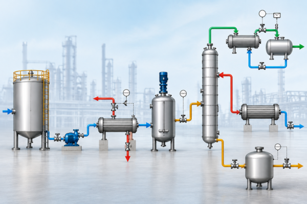
A Process Flow Diagram (PFD) is an engineering drawing used to represent how a process operates. It provides a more detailed view of an industrial process than a Block Flow Diagram (BFD) by showing major equipment, process streams, and important operating information.
While a BFD focuses mainly on the major stages of a process, a PFD introduces the actual major equipment involved and shows how material flows between them.
For example, a simplified process may be represented as:
Feed → Storage Tank → Pump → Heat Exchanger → Reactor → Separation → Product
Each major equipment item and the streams connecting them can be represented on the PFD.
A PFD therefore acts as a bridge between the high-level process concept represented by a BFD and the detailed piping and instrumentation information represented by a Piping & Instrumentation Diagram (P&ID).
What Does a Process Flow Diagram Show?
A typical PFD contains the major information required to understand the operation of a process.
Depending on the project, company standards, and engineering phase, a PFD may include:
- Major process equipment
- Equipment identification numbers
- Process streams
- Stream numbers
- Flow direction
- Feed streams
- Product streams
- Recycle streams
- Waste streams
- Major pumps
- Heat exchangers
- Reactors
- Columns
- Tanks
- Filters
- Separators
- Major valves, where relevant
- Process operating conditions
- Stream flow rates
- Temperature
- Pressure
- Composition
- Mass balance information
- Energy balance information
The exact level of information can vary depending on the purpose of the PFD and the engineering standards being followed.
Equipment Representation in a PFD
One of the major differences between a BFD and a PFD is how equipment is represented.
In a BFD, a single block may represent an entire process section containing several pieces of equipment. In a PFD, major individual equipment items are typically represented separately.
For example:
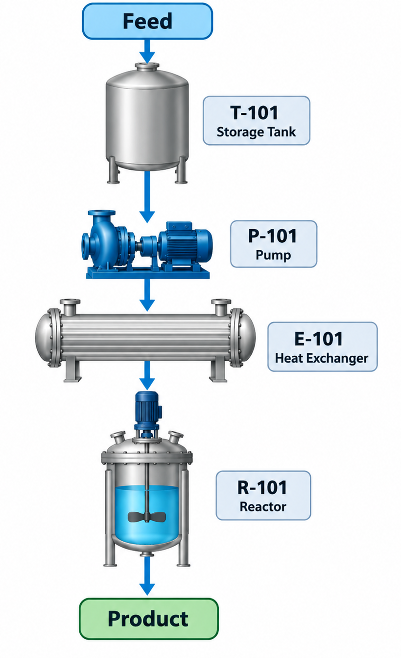
Each major equipment item can have an equipment identification number, such as T-101 for a tank, P-101 for a pump, or E-101 for a heat exchanger.
This allows engineers and project teams to reference specific equipment consistently across engineering documents.
Understanding Process Streams
Process streams are one of the most important elements of a PFD.
A stream represents material flowing from one process unit or equipment item to another. Streams can represent liquids, gases, solids, or mixtures depending on the process.
For example:
Stream 101 → Feed to Reactor
A stream may contain important process information such as:
| Parameter | Example |
| Flow Rate | 10,000 kg/h |
| Temperature | 80°C |
| Pressure | 5 bar |
| Composition | Defined components |
| Phase | Liquid |
These stream properties help engineers understand how the process behaves and provide information required for process calculations.
Flow Direction
A PFD also shows the direction of process flow.
Arrows are typically used to indicate how material moves from one piece of equipment to another.
For example:
Storage Tank → Pump → Heat Exchanger → Reactor
This makes it possible to follow the process from the initial feed through intermediate operations to the final product or waste streams.
Flow direction is particularly important when reviewing the sequence of operations and identifying how different process areas are connected.
Mass Balance in a PFD
A PFD is closely associated with the process mass balance.
A mass balance compares the material entering a process with the material leaving it. For a simplified process:
Feed: 1,000 kg/h
↓
Process
↓
Product: 800 kg/h + Waste: 200 kg/h
The streams should satisfy the relevant material conservation relationships.
Mass balance information can help engineers understand process performance and provide a basis for equipment design and process calculations.
Energy Balance in a PFD
Depending on the process and project stage, a PFD may also include information related to the energy balance.
Energy-related information can include:
- Heating duty
- Cooling duty
- Steam consumption
- Refrigeration duty
- Electrical or mechanical energy
- Heat exchanger duty
Energy balance information is particularly important in processes involving significant heating, cooling, evaporation, condensation, or heat transfer.
For example, a heat exchanger may require a specified heating or cooling duty to achieve the required outlet temperature.
What Does a PFD Usually Not Show?
Although a PFD contains considerably more information than a BFD, it is still not intended to provide the detailed information found in a P&ID.
A typical PFD does not normally show:
- Every valve
- Every instrument
- Detailed control loops
- Instrument signal connections
- Every piping branch
- Detailed valve specifications
- Detailed pipe fittings
- Complete safety instrumentation
- Detailed piping dimensions
These details are developed further in the P&ID and other detailed engineering documents.
The PFD therefore maintains a balance between process understanding and engineering detail.
Why Is a PFD Important?
A PFD helps engineers and project stakeholders answer a fundamental question:
“What equipment is involved, how does material flow between the equipment, and what are the important process conditions?”
Because it combines equipment, streams, and process information, a PFD is an important document throughout process design and project development.
Key Applications of a PFD
PFDs are commonly used for:
- Process design
- Process simulation
- Mass balance
- Energy balance
- Equipment sizing
- Equipment selection
- Process review
- Design review
- Cost estimation
- Technical proposals
- Project development
A well-developed PFD can also help different engineering disciplines understand the overall process before detailed design begins.
PFD and Equipment Sizing
The information represented in a PFD can provide an important basis for equipment sizing and selection.
For example:
Flow Rate → Pump Sizing
The required process flow can help determine the appropriate pump capacity.
Heat Duty → Heat Exchanger Sizing
The required heating or cooling duty can support heat exchanger design calculations.
Residence Time + Flow Rate → Tank or Reactor Sizing
The required residence time and process flow can be used to determine the necessary vessel volume.
Gas Flow + Operating Conditions → Compressor or Blower Sizing
Gas flow rate, pressure, temperature, and other operating conditions can support compressor or blower selection.
The PFD itself does not necessarily contain every detailed sizing calculation, but the information it represents can serve as an important input to downstream engineering.
PFD vs. BFD
A Block Flow Diagram (BFD) provides a high-level view of the process, while a Process Flow Diagram (PFD) adds major equipment and important process information.
| Feature | BFD | PFD |
| Major Process Stages | ✓ | ✓ |
| Major Equipment | Limited/Grouped | ✓ |
| Equipment Identification | Usually No | ✓ |
| Process Streams | Basic | ✓ |
| Flow Direction | ✓ | ✓ |
| Stream Conditions | Usually Limited | ✓ |
| Mass Balance | Usually No | ✓ |
| Energy Information | Limited | ✓ |
| Detailed Instrumentation | No | No |
In simple terms:
BFD = Major process stages and connections
PFD = Major equipment, process streams, and key process conditions
P&ID = Detailed piping, instrumentation, and control
Where Does the PFD Fit in Engineering?
The PFD typically follows the development of the BFD and precedes the P&ID.
A simplified engineering progression is:
Process Concept → BFD → PFD → P&ID → Detailed Engineering
Each stage introduces a greater level of engineering detail.
- Process Concept
Defines the overall process approach and objectives.
- Block Flow Diagram
Shows the major process stages and their relationships.
- Process Flow Diagram
Introduces major equipment, process streams, and important operating information.
- Piping & Instrumentation Diagram
Adds detailed piping, valves, instruments, control loops, and process connections.
- Detailed Engineering
Develops the information required for equipment, piping, electrical, instrumentation, structural, construction, and other engineering disciplines.
This structured progression helps engineers move from a broad process concept toward a detailed and constructible design.
Key Takeaway
A Process Flow Diagram (PFD) provides a detailed representation of how an industrial process operates by showing major equipment, process streams, flow direction, and important process conditions.
It goes beyond the conceptual blocks of a BFD while remaining less detailed than a P&ID.
A PFD answers the key question:
“What major equipment performs the process, how are they connected, and what are the important process conditions?”
By providing this information, a PFD supports process design, equipment sizing, mass and energy balances, design reviews, cost estimation, and the development of detailed engineering documents.

With nearly two decades of experience in engineering, I bring deep expertise across both EPC (Engineering, Procurement, and Construction) and product-based OEM environments. My core strengths lie in engineering standardization, process optimization, and technical leadership. I have consistently driven excellence through the development and implementation of robust engineering frameworks, delivering value across global industrial projects and complex product lifecycles.