
Introduction
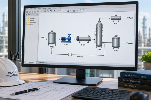
A Block Flow Diagram (BFD) is one of the simplest ways to represent an industrial process. It provides a high-level visual representation of how major process stages are connected, allowing engineers and other stakeholders to understand the overall process without getting into detailed engineering information.
Unlike detailed engineering diagrams, a BFD groups related operations and equipment into major process blocks. It focuses on the overall process logic, showing how materials move from the initial feed through different process stages to the final product or output.
For example, a water-treatment process can be represented as:
Raw Water → Pretreatment → Biological Treatment → Filtration → Disinfection → Treated Water
Each block represents a collection of processes, equipment, or operations that perform a specific function.
The purpose of a BFD is not to show exactly how a plant will be constructed. Instead, it communicates what the major process stages are and how they are connected.
What Does a Block Flow Diagram Show?
A typical BFD focuses on the major elements needed to understand the overall process. Depending on the project and its level of development, it may include:
- Major process blocks
- Main feed streams
- Major intermediate streams
- Product streams
- Waste streams
- Recycle streams
- Major process connections
- Direction of material flow
- Major chemicals or utilities, when relevant
The key principle is that a BFD focuses on process logic rather than detailed equipment or piping information.
Simple BFD Example
A basic process can be represented as:
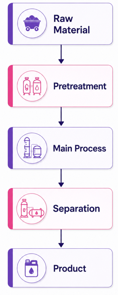
This simple representation allows stakeholders to understand the sequence of major operations at a glance.
What Does a BFD Not Show?
A Block Flow Diagram is intentionally high-level. It does not normally include the detailed engineering information required for equipment selection, piping design, or instrumentation.
A typical BFD does not show:
- Individual pumps
- Individual valves
- Detailed piping
- Instrumentation
- Control loops
- Pipe sizes
- Valve sizes
- Equipment dimensions
- Detailed operating conditions
- Detailed stream compositions
- Detailed mass-balance information
These details are introduced progressively in more detailed engineering documents such as Process Flow Diagrams (PFDs) and Piping and Instrumentation Diagrams (P&IDs).
Why Is a Block Flow Diagram Important?
The main value of a BFD is that it provides a quick understanding of the overall process.
Engineers, project managers, clients, and other stakeholders can use a BFD to answer important questions such as:
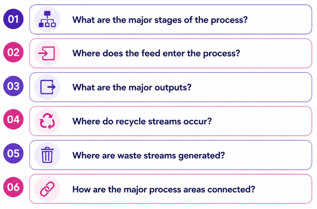
Because it removes unnecessary detail, a BFD makes complex industrial processes easier to understand during the early stages of a project.
When Is a BFD Used?
BFDs are particularly useful during:
- Concept development
- Feasibility studies
- Preliminary process design
- Process planning
- Project discussions
- Early-stage engineering reviews
- Communication between technical and non-technical stakeholders
Understanding Process Blocks in a BFD
One of the defining characteristics of a BFD is the use of process blocks.
A process block can represent different levels of a process depending on the purpose of the diagram. For example, a block could represent:
- A single major operation
- A group of equipment
- A complete process area
- A treatment stage
- A reaction section
- A separation section
The appropriate level of detail depends on what the BFD is intended to communicate.
Do BFD Blocks Represent Individual Equipment?
Not necessarily.
A common misconception is that every box in a BFD represents one physical piece of equipment. In reality, a block generally represents a process function or group of related operations.
For example, a block labeled “Distillation Section” could include:
- Distillation column
- Reboiler
- Condenser
- Reflux drum
- Pumps
- Associated piping
Instead of showing each component individually, the BFD represents them as one major process section.
This keeps the diagram simple while still communicating the overall process structure.
BFD vs. Equipment Diagram
A BFD should not be confused with an equipment layout or detailed equipment diagram.
An equipment diagram focuses on individual physical components, whereas a BFD focuses on what the process does and how its major stages are connected.
For example:
BFD:
Raw Water → Pretreatment → Filtration → Disinfection → Treated Water
Detailed Engineering:
Pumps → Valves → Filters → Pipes → Instruments → Control Loops → Tanks
The BFD provides the overall process architecture, while detailed engineering documents provide the information required to design and construct the system.
Where Does the BFD Fit in the Engineering Process?
A BFD is generally created during the early stages of process development and becomes a foundation for progressively more detailed engineering documentation.
A simplified engineering progression is:
Process Concept → BFD → PFD → P&ID → Detailed Engineering
Each stage adds another level of engineering information.
- Process Concept
Defines the overall process approach and major objectives.
- Block Flow Diagram
Defines the major process stages and their relationships.
- Process Flow Diagram
Adds greater detail about equipment, process streams, operating conditions, and other process information.
- Piping & Instrumentation Diagram
Adds detailed piping, valves, instrumentation, control loops, and process connections.
- Detailed Engineering
Develops the information required for equipment, piping, electrical, instrumentation, structural, construction, and other engineering disciplines.
This progression allows engineers to move from a broad process concept to a detailed design in a structured manner.
BFD vs. PFD vs. P&ID
Understanding the difference between these diagrams is important because each serves a different engineering purpose.
| Diagram | Primary Purpose | Level of Detail |
| BFD | Shows major process stages and connections | Low |
| PFD | Shows process flow, equipment, and key process information | Medium |
| P&ID | Shows detailed piping, instrumentation, and controls | High |
In simple terms:
BFD = What are the major process stages?
PFD = How does the process operate?
P&ID = How is the process connected and controlled?
Benefits of Using a BFD
A well-developed Block Flow Diagram provides several benefits during early engineering and project planning.
Simplifies Complex Processes
Large industrial processes can involve hundreds or thousands of components. A BFD reduces this complexity into a manageable number of major process blocks.
Improves Communication
Because the diagram is easy to understand, it can be used to communicate the process concept between engineers, project managers, clients, and other stakeholders.
Supports Early Design Decisions
A BFD helps teams evaluate the overall process arrangement before investing time in detailed engineering.
Provides a Foundation for Detailed Engineering
The major process structure established in the BFD can serve as a starting point for developing PFDs, P&IDs, and subsequent engineering documentation.
Key Takeaway
A Block Flow Diagram (BFD) provides a high-level view of an industrial process by representing major operations as connected process blocks.
It answers one fundamental question:
“What are the major stages of the process, and how are they connected?”
Unlike detailed engineering diagrams, a BFD intentionally leaves out individual equipment, valves, instrumentation, pipe sizes, and control loops.
Its simplicity is its strength. By establishing the overall process architecture before detailed engineering begins, a BFD helps teams understand, communicate, review, and develop complex industrial processes more effectively. BFD Diagram Block Flow Diagram

With nearly two decades of experience in engineering, I bring deep expertise across both EPC (Engineering, Procurement, and Construction) and product-based OEM environments. My core strengths lie in engineering standardization, process optimization, and technical leadership. I have consistently driven excellence through the development and implementation of robust engineering frameworks, delivering value across global industrial projects and complex product lifecycles.